Index


Reprinted for private circulation from
JOURNAL OF DENTAL RESEARCH
Vol. 41, No. 2, March—April 1962

Copyright 1962 by International Association for Dental Research

PRINTED IN U.S.A.

Structural Density of

Compacted Gold Foil and Mat Gold

J. TURNBAUGH HODSON and GERALD D. STIBBS Department of Operative Dentistry, University of Washington,

School of Dentistry, Seattle, Washington

Gold foil is universally recognized as an excellent dental restorative material when the indications and manipulative techniques are proper? Because interest has been expressed in the use of mat gold under similar conditions, examination of the two materials was undertaken through the use of hardness measurement on specimens of compacted gold foil and mat gold. 2, 3

The purpose of the study was to obtain quantitative information on the structural density of the golds when compacted under dental techniques. Hardness is a measurable quality that is related to the density and plasticity of metals. 4-7 Brinell hardness has been used on gold foil by several investigators .8-15 Other methods for studying the condensation of gold foil have included Rockwell, Knoop, and Vickers hardness. 16-18

The dental condensation of gold foil is comparable to the metallurgical compaction of powders. "Condensation" and "compaction" are used synonymously in this report; "density" refers to the relative solidity or porosity of specimens.

MATERIALS AND METHODS

Forty specimens were prepared by five dentists who were experienced in the use of gold foil. Their skill in technique was expected to compensate for difficulties in packing the gold materials and thereby obtain the most optimum compaction. Details of technique were left to the discretion of the individual operators, on condition that both golds should receive equal treatment, consistent with clinical procedures.

Methyl methacrylate mounts* were shaped with flattened walls for securing in a bench vise during preparation of the cavity and compaction of the gold.

Rectangular cavities measuring approximately 2 mm. in width by 3.5 mm. in length and 1.5 mm. in depth were cut by hand with dental instruments. The cavity forms were prepared by each operator for the specimens which he condensed. Two specimens of gold foil and two of mat gold were prepared in each mount. Four foil and four mat specimens were condensed by each operator. Three operators used hand malleting, and two operators used a pneumatic mechanical condenser. Number 4 sheet foil+ and crystalline mat gold++ were used in the experiment.


Presented before the Dental Materials Group at the I.A.D.R. meeting in Chicago, March 19, 1960. Received for publication July 7, 1960.

* Lucite.

+ Morgan, Hastings and Co., Philadelphia, Pennsylvania.

++ Williams Gold Refining Co., Buffalo, New York.


Final preparation for hardness measurement followed A.S.T.M. procedures.19 Care was taken to avoid heating or work hardening the small specimens as the surface was leveled by hand grinding through 4/0 emery paper, polished at slow speed with levigated alumina, and finished with a silicon compound.*

The specimens were measured in two rows of indentations across the polished surface with a microhardness tester.+Ten or more impressions were obtained on each specimen with a test load of 0.5 kg. The Vickers diamond pyramid hardness numbers were calculated by dividing the applied load in kilograms by the surface area of the impression in square millimeters, computed from the average of the two measured diagonals of the impression. Hardness numbers were calculated for 474 indentations. After the hardness measurements were taken, some of the specimens were prepared for study with the microscope by removing the polished surface with aqua regia to reveal the underlying structures.

RESULTS AND DISCUSSION

Hardness.--The average hardness for the specimens from each operator is given in Table 1. The final Vickers hardness was 61 for compacted gold foil and 62 for mat

TABLE 1

HARDNESS OF COMPACTED GOLD FOIL AND MAT GOLD

Operator

Specimen

No.

Mean Foil

Hardness

Mean Mat

Hardness

Method of

Condensation

condenser Points

Diameter (Mm.)

1

25-29

66

71

Pneumatic

0.5

2

5-8

63

75

Pneumatic

0.5

3

9-11

61

58

Hand mallet

0.4 and 0.5

4

1-4

58

62

Hand mallet

0.4- 1.0

5

17-20

58

43

Hand mallet

0.4-1.0

Final Av


61

62


gold. The closeness of these figures indicates that both forms of gold are capable of achieving the same degree of strain hardening and density. In practice, no single specimen or technique produced uniform density, and the hardness values varied accordingly.

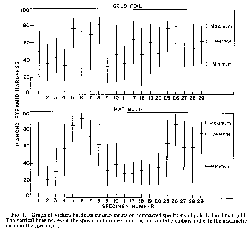
The maximum, minimum, and mean hardnesses of individual specimens are presented in Figure 1. The length of each vertical line indicates the spread in density between the greatest and smallest measurement on a specimen. The arithmetic mean hardness is plotted as a short horizontal bar across the vertical line. The operator and method of preparation for these specimens are given in Table 1.

There was a definite upper limit to hardness. Regardless of technique or force, none of the specimens exceeded 100 Vickers hardness. This was taken as a measure of the amount of strain hardening produced in the gold materials during compaction. It did not necessarily indicate complete density in the specimen. The density and texture of solid gold were achieved only in localized areas which were usually surrounded by voids.

* M309W, American Optical Co., New York, New York.

++ Kentron Micro-Hardness Tester, Kent Cliff Laboratories, Peekskill, New York.


The remarkable difference in hardness between gold foil and mat gold Specimens 17–20 in Figure 1 was due to a difference in the size of condenser points. The large foot condenser was used on the mat-gold specimens. It produced a fairly uniform density, as shown by the short length on the vertical scale, but the gold was loosely compacted. The gold-foil specimens were condensed in the same manner except that a 0.4-mm. condenser was used. The mounts were held in a bench vise during hand malleting of the specimens.

Other variations in technique were revealed by the measurements. Specimens 9–11 were held by hand on a folded towel during compaction. The bench vise was used for Specimens 1–4, but condensation techniques were varied for each pair of specimens. Specimens 5–8 and 25–29 were held in a bench vise and compacted with the pneumatic condenser.

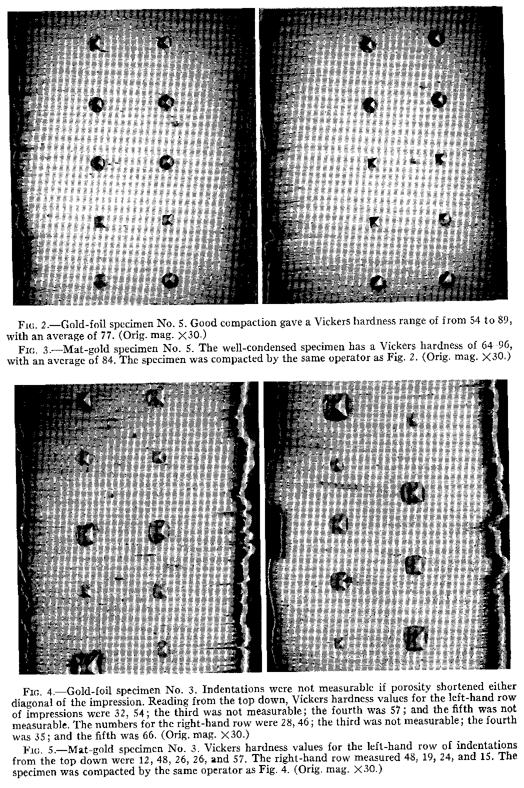
Differences in personal techniques were shown by the distribution of hardness. One operator tended to produce hardness in the center of gold-foil specimens and at the margins of mat-gold specimens. Consistent high hardness was achieved by another operator through careful and systematic stepping of the condenser (Figs. 2 and 3). However, a crevice measuring approximately 0.5 mm. in length was located near the

Picture


Picture


point angle of one well-condensed specimen, even though the gold surrounding the void was very dense. Such areas were shown by the size of the hardness indentations (Figs. 4 and 5). Large impressions indicate porosity and low hardness.

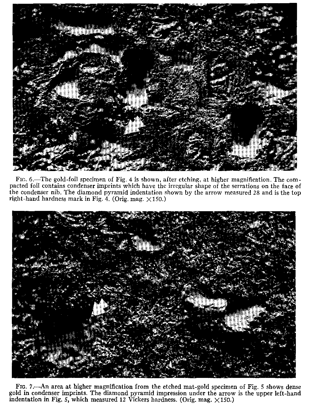
Microstructure.—The specimens contained similar structures when examined under the microscope (Figs. 6 and 7). Gold foil had a laminated appearance and the mat

Picture


gold contained broken crystal fibers. Porosities were located between the layers of foil, around the mat-gold crystallites, and in the sides of the diamond pyramid hardness impressions.

An unexpected feature was the presence of imprints from the condenser. They were distinguished by the shape of the serrations on the face of the condenser nib. Smooth, dense gold was formed at the base of the imprints under the impact of the condenser. This was the most solid gold in the specimens.

SUMMARY

The compaction of gold foil and mat gold into a cavity created similar structures of dense gold and voids. Hardness measurements varied in numerical values because of porosities. Although qualified numbers were difficult to obtain, the hardness indentations were useful for mapping hard and soft areas in specimens. A more convenient method was to remove the surface with aqua regia and examine the underlying structures with the microscope. Results indicated that the theoretical ideal of a dense and solid gold restoration was not achieved with either gold foil or mat gold.

The authors wish to thank Drs. A. F. Dolan, J. M. Grey, L. E. Ostlund, and Mr. Charles Schroeter, of the School of Dentistry, for their help in making the specimens, and Dr. Earl C. Roberts, professor of metallurgical engineering, for his assistance in the project.

REFERENCES

1. STIBBS, G. D. Appraisal of the Gold Foil Restoration, J. Am. Acad. Gold Foil Operators, 2:20, 1959.

2. Hodson, J. T., and STIBBS, G. D. Structural Density of Compacted Gold Foil and Mat Gold, J. D. Res., 39:765, 1960 (abstr.).

3. Hodson, J. '1'. Microstructure of Gold Foil and Mat Gold, D. Progress, 2:55, 1961.

4. KEHL, G. L. Principles of Metallograpltic Laboratory Practice, chap. 1, p. 6. 3d ed. New York: Mc-Graw-Hill Book Co., Inc., 1949.

5. SKINNER, E. W., and PHILLIPS, R. W. The Science of Dental Materials, chap. 19. 5th ed. Philadelphia: W. B. Saunders Co., 1960.

6. PEYTON, F. A., ANTHONY, D. H., ASGAR, K., CHARBENAU, G. T., CRAIG, R. G., and MYERS, G. E. Restorative Dental Materials, chap. 8. St. Louis: C. V. Mosby Co., 1960.

7. SOUDER, W., and PAFFENBARGER, G. C. Physical Properties of Dental Materials, pp. 34-36, 54-56.

(National Bureau of Standards Circ. C433.) Washington, D.C.: Government Printing Office, 1942.

8. HARTMAN, L. L. Controlling Factors in Manipulation of Gold Foil, J.A.D.A., 21.:816, 1934.

9. SMITH, J. C. The Chemistry and Metallurgy of Dental Materials, pp. 45-47. Oxford: Blackwell Scientific

Publications, Ltd., 1946.

10.Rule, R. W. Preliminary Report of Tests Made To Determine Physical Properties and Clinical Values of Gold and Platinum Foil, Foil,J.A.D.A., 23:93, 1936

11. Gold Foil and Platinum-centered Foil: Methods of Condensation, ibid., 24:1783, 1937.

12. A Further Report on Physical Properties and Clinical Values of Platinum-centered Gold Foil as Compared to Pure Gold Filling Materials, ibid., p. 583.

13. SHELL, J. S. Properties and Microscopic Structure of Gold and Gold-Platinum Foils, J.A .D.A., 24; 596, 1937.

14. Physical Properties of Malleted Gold Foil and 24k. Gold Fillings. (Research Department Report.) Hartford: J. M. Ney Co., June 25, 1937.

15. Mat Gold. (Research Report No. 1002.) Buffalo: Williams Gold Refining Co.

16. STROSNIDER, C. W. Comparison of Specific Gravities and Hardness of Cohesive Gold Foil Malleted with Various Types of Condensers, J. D. Res., 24:61, 1945.

17. Koser, J. R., and INGRAHAM, R. Mat Gold Foil with a Veneer Cohesive Gold Foil Surface for Class V Restorations, J.A.D.A., 52:714, 1956.

18. KRAMER, W. S., TRANDELL, T. R., and DIEFENDORF, W. L. A Comparative Study of the Physical Properties of Variously Manipulated Gold Foil Materials, J. Am. Acad. Gold Foil Operators, 3:8, 1960.

19. A.S.T.M. Standards 1958, Part 3: Methods of Testing Metals (except Chemical Analysis), pp. 52-57. Philadelphia: American Society for Testing Materials, 1958.
Index